
1.
构建有一个 3-bit input的电路,然后根据下图输出一个2-bit的向量,和三个单独的 1-bit输出。注意在下图中,旁边带有数字的刻度线表示向量的宽度。
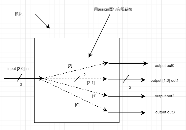
|
1 2 3 4 5 6 7 8 9 10 |
module top_module ( input wire [2:0] in, output wire [1:0] out1, output wire out0, output wire out2, output wire out3 ); //使用assign语句实现 endmodule |
2.
构建一个组合电路,将输入的32位输入( [31:0] )分成两个16-bit的高位输出[31:16] 和低位输出[15:0]。
|
1 2 3 4 5 6 7 |
module top_module( input wire [31:0] in, output wire [15:0] out_hi, output wire [15:0] out_lo ); //使用assign语句实现 endmodule |
3.
交换一个32位输入的端序,并输出。比如输入向量是大端,输出的向量应该为小端;如果输入的向量是小端,输出的向量应该为大端,比如:
out [31:0] in[31:0]
|
1 |
AaaaaaaaBbbbbbbbCcccccccDddddddd => DdddddddCcccccccBbbbbbbbAaaaaaaa |
|
1 2 3 4 5 6 7 |
module top_module( input [31:0] in, output [31:0] out ); //使用assign语句实现 endmodule |
4.
对输入向量a和b分别作按位操作或(bitwise OR)和逻辑或(logical OR),a和b按位取反(bitwise inverse )和a逻辑否定(取非)的结果输出。
|
1 2 3 4 5 6 7 8 9 10 11 12 13 |
module top_module( input [2:0] a, input [2:0] b, output [2:0] or_bitwise, output or_logical, output [2:0] not_a, output [2:0] not_b, output logical_not_a ); //使用assign语句实现 endmodule |
5.
对一个有四个输入的组合电路,in[3:0]。
输出:
out_and:四个输入相与的输出。
out_or:四个输入相或的输出。
out_xor:四个输入相异或的输出。
|
1 2 3 4 5 6 7 8 9 10 |
module top_module( input [3:0] in, output out_and, output out_or, output out_xor ); //使用assign语句实现 endmodule |
6.
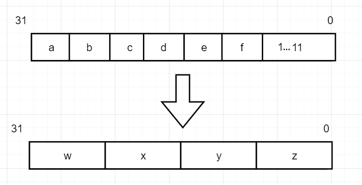
位拼接操作符练习:下图中a,b,c,d,e,f都是4-bit的输入,最后在剩余的位数上补1。w,x,y,z都是8-bit输出向量。要求将给定的输入向量连接在一起,
|
1 2 3 4 5 6 7 |
module top_module ( input [3:0] a, b, c, d, e, f, output [7:0] w, x, y, z ); //assign {... } = { ...}; endmodule |
7.
使用位拼接操作符将8-bit输入向量a颠倒每一位的顺序。比如:a为8’b10011111,颠倒位序后应该为8’b11111001。
|
1 2 3 4 5 6 7 8 |
module top_module( input [7:0] a, output [7:0] b ); //使用assign语句实现 endmodule |
8.
使用位拼接运算符,将8-bit有符号数输入向量a,转换为32-bit有符号向量b。注意符号位的扩展。
|
1 2 3 4 5 6 7 |
module top_module ( input [7:0] a, output [31:0] b ); // assign b = {...}; endmodule |
9.
将下图由拼接和复制5个输入创建的两个向量的同或(XNOR)结果输出到out。
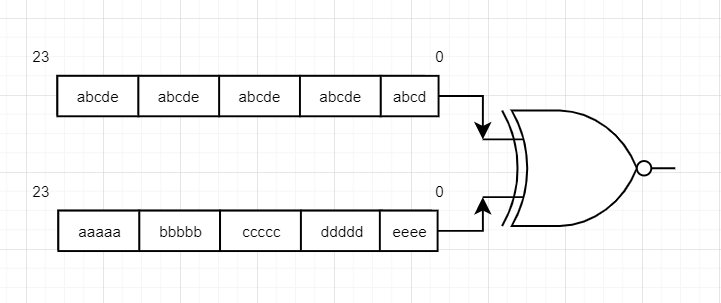
|
1 2 3 4 5 6 7 8 |
module top_module ( input a, b, c, d, e, output [23:0] out ); //输出是通过拼接和复制5个输入创建的两个向量的同或(XNOR)结果。 //assign out = { ... } ~^ { ... }; endmodule |
对应视频: