
1.
用两段式或三段式状态机代码描述实现下图摩尔状态机。要点如下:
- areset:高电平异步复位信号,将状态复位到B
- 状态机内有两个状态:A,B。A = 0,B = 1

完善下列代码:
|
1 2 3 4 5 6 7 8 9 10 11 12 13 14 15 16 17 18 19 20 21 22 |
module top_module( input clk, input areset, input in, output out ); parameter A=0, B=1; reg state, next_state; //状态机第一段 //always @(posedge clk, posedge areset)... //状态机第二段 //always @(*)... //输出 //assign out = (state == ...); endmodule |
参考代码:
[content_control]
[/content_control]
仿真testbench:
[content_control]
[/content_control]
2.
用两段式或三段式状态机代码描述实现下图摩尔状态机。要点如下:
- areset:高电平异步复位信号,将状态复位到OFF
- 注意有两个输入j和k
- 状态机内有两个状态:OFF,ON。OFF= 0,ON = 1

完善下列代码:
|
1 2 3 4 5 6 7 8 9 10 11 12 13 14 15 16 17 18 19 20 21 |
module top_module( input clk, input areset, input j, input k, output out ); parameter OFF=0, ON=1; reg state, next_state; //状态机第一段 //always @(posedge clk, posedge areset).. //状态机第二段 //always @(*).. //输出 //assign out = (state == ...); endmodule |
参考代码:
[content_control]
[/content_control]
仿真testbench:
[content_control]
[/content_control]
3.
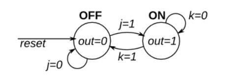
将问题2中的高电平异步复位改为高电平同步复位信号,如下图所示:
完善下列代码:
|
1 2 3 4 5 6 7 8 9 10 11 12 13 14 15 16 17 18 19 20 21 |
module top_module( input clk, input reset, input j, input k, output out ); parameter OFF=0, ON=1; reg state, next_state; //状态机第一段 //always @(posedge clk).. //状态机第二段 //always @(*).. //输出 //assign out = (state == ...); endmodule |
4.
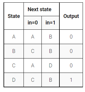
根据下表,仅实现此状态机的状态转移逻辑和输出逻辑(都为组合逻辑部分)。 给定当前状态(state),根据状态转移表计算 next_state 和 output(out)。
注意使用下列状态编码: A=2’b00,B=2’b01,C=2’b10,D=2’b11
|
1 2 3 4 5 6 7 8 9 10 11 12 13 14 |
module top_module( input in, input [1:0] state, output [1:0] next_state, output out ); parameter A=0, B=1, C=2, D=3; //实现状态转移逻辑 //实现输出逻辑 endmodule |
参考代码:
[content_control]
[/content_control]
仿真testbench:
[content_control]
[/content_control]
5.
在问题4的基础上,完成这个状态机(补充状态机的状态触发器),注意添加上高电平同步复位信号reset。
|
1 2 3 4 5 6 7 8 9 |
module top_module( input clk, input in, input reset, output out ); endmodule |
参考代码:
[content_control]
[/content_control]
6.
状态机中常用独热码(one-hot code)编码状态,比如: A=4’b0001,B=4’b0010,C=4’b0100,D=4’b1000,尝试用独热码编码状态重新实现问题4。
举例说明如下:考虑Next state为A可能实现的路径有两条:
- State是A,in = 0
- State是C,in = 0
因为next_state中A的状态只需要关系bit 0,所以next_state(A) = next_state[0]
所以得到Next State为A的情况是:assign next_state[0] = state[0] & (~in) | state[2] & (~in);

根据以上的分析,完善以下代码:
|
1 2 3 4 5 6 7 8 9 10 11 12 13 14 |
module top_module( input in, input [3:0] state, output [3:0] next_state, output out ); // A状态转移逻辑 assign next_state[0] = state[0]&(~in) | state[2]&(~in); // 输出 assign out = ... endmodule |
参考代码:
[content_control]
[/content_control]
仿真testbench:
[content_control]
[/content_control]
7.
参考问题6,用独热码(one-hot code)编码状态实现下图状态的状态转移逻辑和输出逻辑(都为组合逻辑部分)。

完善以下代码:
|
1 2 3 4 5 6 7 8 9 10 11 12 13 14 15 16 |
module top_module( input in, input [9:0] state, output [9:0] next_state, output out1, output out2 ); // A状态转移逻辑 assign next_state[0] = ... // 输出 assign out1 = ... assign out2 = ... endmodule |
参考代码:
[content_control]
[/content_control]
[content_control]
[/content_control]
8.(简单检测帧起始)
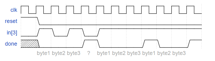
实现一个抓取完整3个字节数据段(每抓取完整的3个byte,输入一个单时钟周期脉冲的done信号)的带有高电平同步复位信号状态机。检查该数据段初始字节(byte 1)特点如下:在8-bit输入向量in中,in[3]为1。示例波形图如下所示:

如果有错误发生,重新抓捕初始字节

重叠序列出现时,比如在byte 1和byte 3中in[3]出现多次高电平时,输出done信号只跟随第一次出现的高电平,也就是说,忽略重叠序列。如下图所示:
完善以下代码:
|
1 2 3 4 5 6 7 8 9 |
module top_module( input clk, input [7:0] in, input reset, output done ); endmodule |
参考代码:
[content_control]
[/content_control]
参考状态转移图:
[content_control]

[/content_control]
仿真testbench:
[content_control]
[/content_control]
9.
将问题8中抓取到的3个字节的数据都保存下来,与done信号一起同步输出,如下图所示:

|
1 2 3 4 5 6 7 8 9 10 11 |
module top_module( input clk, input [7:0] in, input reset, output [23:0] out_bytes, output done ); // 问题8中的状态机可以重复使用 endmodule |
参考代码:
[content_control]
[/content_control]
仿真testbench:
[content_control]
[/content_control]
对应视频: