
上几节内容介绍了UART的组成部分发送(tx.v), 接收(rx.v)以及波特率发生器(bd_rate_en.v)等原理及代码,本节内容介绍如何将各个模块组装在一起形成一个完整的UART收发系统UART.v。组装后的结果如图1 所示。根据图1的结构,下面将进行程序组装,并提供仿真与实验结果。
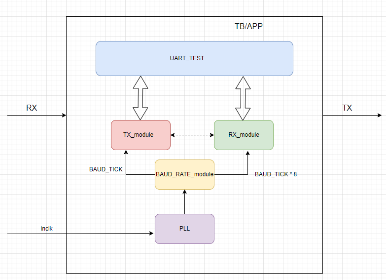
图1
一 rx采用中心对齐的模块。
- UART组装的程序
|
1 2 3 4 5 6 7 8 9 10 11 12 13 14 15 16 17 18 19 20 21 22 23 24 25 26 27 28 29 30 31 32 33 34 35 36 37 38 39 40 41 42 43 44 45 46 47 48 49 50 51 52 53 54 55 56 57 58 59 60 61 62 63 64 65 66 67 68 69 70 71 72 73 74 75 76 77 78 79 80 81 82 83 84 85 86 87 88 89 90 91 92 93 94 95 96 97 98 99 100 101 102 103 104 105 106 107 108 109 110 111 112 113 114 115 116 117 118 119 120 121 122 |
`timescale 1ns / 1ps module uart #( parameter BAUD_TICK = 115200, parameter STOP_BIT = 1, parameter PARITY = "NONE" ) ( input inclk, input tx_req, input [7:0] tx_data, output tx_ack, output tx, input rx, //rx 端在本设计中没有实现 output rx_rdy, output [7:0] rx_data, output sys_clk, //将系统时钟输出,便于测试程序使用 output rst ); wire tx_bd_en; wire rx_bd_en; wire locked; assign rst=!locked; uart_pll uart_pll_inst ( .areset (1'b0), .inclk0 (inclk), // inclk ----50M, .c0 (sys_clk), // sys_clk----72M .locked (locked) ); baud_rate_en #( .BAUD_RATE (BAUD_TICK), // 波特率:115200 .FREQUENCY (72000000) // 时钟参数:72M ) bau_rate_en_inst ( .clk (sys_clk), .baud_tick (BAUD_TICK), .bt_en (0), .tx_bd_en (tx_bd_en), .rx_bd_en (rx_bd_en), .rst (rst) ); //========================================================================= tx #( .PARITY (PARITY), .STOP_BIT (STOP_BIT) ) txd_inst ( .clk (sys_clk), .tx_bd_en (tx_bd_en), .tx_data (tx_data), .tx_req (tx_req), .tx_ack (tx_ack), .tx (tx), .rst (rst) ); `define CENTER_ALIGNMENT `ifdef CENTER_ALIGNMENT rx #( .PARITY (PARITY), //"ODD"--odd parity, "EVEN"--even parity, others--no parity .STOP_BIT (STOP_BIT) ) rx_inst ( .sys_clk (sys_clk), .bd8_rate (rx_bd_en), .rx_data (rx_data), .rx_rdy (rx_rdy), .rx (rx), .rst (rst) ); `else rx_more_one #( .PARITY (PARITY), //"ODD"--odd parity, "EVEN"--even parity, others--no parity .STOP_BIT (STOP_BIT) ) rx_more_one_inst ( .sys_clk (sys_clk), .bd8_rate (rx_bd_en), .rx_data (rx_data), .rx_rdy (rx_rdy), .rx (rx), .rst (rst) ); `endif //========================================================================= endmodule |
2. test_uart.v 程序
- 本测试程序将仿真程序和板载测试程序合二为一。
- 仿真数据由本程序产生,通过tx module 串行发送到 tx pin 上。 通过回环方式由rx module 进行串行接收,即:rx <= tx。为了方便测试,在仿真中每包只有8个数据。
- 板载测试数据由计算机产生,通过rx module 进行串行接收。将接收到的并行数据回环到tx module。

图2
从图2 中可以看出:
1)初始化使用变量,
如果是SIM_DEBUG 模式, 等待16000时钟周期后,tx_data = 0; tx_req = 1; 发送第一笔数据;
如果是正常接收模式,等待rx_rdy_r == 1, tx_data = rx_data_r; tx_req = 1; rx_ack = 1; 发送从接收端得到的数据。
2)rx_ack = 0; 等待发送模块tx.v 返回tx_ack 信号, 如果tx_ack == 1 , 发送请求信号 tx_req = 0;
3)等待tx_ack 是否为0, 如果tx_ack == 0 ,
如果是SIM_DEBUG 模式, 查看目前是否已经发送过 8个数据了(tx_data = 0~7), 如果已经发送过8个数据,返回状态0
如果是正常接收模式,跳转状态3
4)tx_cnt 清零,
如果是SIM_DEBUG 模式, 数据 + 1; 发送tx_req = 1; 返回到状态1
如果是正常接收模式,等待是否有新的数据被接收, 发送tx_req = 1; 同时将rx_ack = 1 ; 通知rx rx_data_r数据已经被接收到了, 返回到状态1
|
1 2 3 4 5 6 7 8 9 10 11 12 13 14 15 16 17 18 19 20 21 22 23 24 25 26 27 28 29 30 31 32 33 34 35 36 37 38 39 40 41 42 43 44 45 46 47 48 49 50 51 52 53 54 55 56 57 58 59 60 61 62 63 64 65 66 67 68 69 70 71 72 73 74 75 76 77 78 79 80 81 82 83 84 85 86 87 88 89 90 91 92 93 94 95 96 97 98 99 100 101 102 103 104 105 106 107 108 109 110 111 112 113 114 115 116 117 118 119 120 121 122 123 124 125 126 127 128 129 130 131 132 133 134 135 136 137 138 139 140 141 142 143 144 145 146 147 |
`timescale 1ns / 1ps module test_uart # ( parameter SIM_DEBUG = "FALSE" // "TRUE" "FALSE" ) ( input inclk, output tx, input rx ); parameter PARITY = "NONE"; parameter STOP_BIT = 1; wire rst; wire sys_clk; wire tx_ack; reg [7:0] tx_data = 0; reg tx_req = 0; wire [7:0] rx_data; wire rx_rdy; reg rx_rdy_r = 0; reg [7:0] rx_data_r = 0; reg rx_ack = 0; always @ (posedge sys_clk) if(rst) begin rx_rdy_r <= 0; end else begin if(rx_ack) rx_rdy_r <= 0; else if(rx_rdy) begin rx_rdy_r <= 1; rx_data_r <= rx_data; end end reg [31:0] tx_cnt = 0; reg [2:0] tx_st = 0; always @ (posedge sys_clk) if(rst) begin rx_ack <= 0; tx_cnt <= 0; tx_data <= 0; tx_req <= 0; tx_st <= 0; end else case (tx_st) 0: begin rx_ack <= 0; tx_data <= 0; tx_req <= 0; if(SIM_DEBUG == "TRUE") begin tx_cnt <= tx_cnt + 1; if(tx_cnt == 16000) begin tx_req <= 1; tx_st <= 1; end end else if(rx_rdy_r) begin tx_data <= rx_data_r; tx_req <= 1; rx_ack <= 1; tx_st <= 1; end end 1: begin rx_ack <= 0; if(tx_ack) begin tx_req <= 0; tx_st <= 2; end end 2: begin if(!tx_ack) begin if((tx_data == 7) && (SIM_DEBUG == "TRUE") ) tx_st <= 0; else tx_st <= 3; end end 3: begin tx_cnt <= 0; if(SIM_DEBUG == "TRUE") begin tx_data <= tx_data + 1; tx_req <= 1; tx_st <= 1; end else if(rx_rdy_r) begin tx_data <= rx_data_r; tx_req <= 1; rx_ack <= 1; tx_st <= 1; end end default: tx_st <= 0; endcase uart #( .STOP_BIT (STOP_BIT), .PARITY (PARITY) ) uart_inst ( .inclk (inclk), .tx_req (tx_req), .tx_data (tx_data), .tx_ack (tx_ack), .tx (tx), .rx (rx), .rx_rdy (rx_rdy), .rx_data (rx_data), .sys_clk (sys_clk), .rst (rst) ); endmodule |
2. 仿真
仿真时采用回环的方式,即TX与RX信号在tb.v内实现回环,如图2所示。
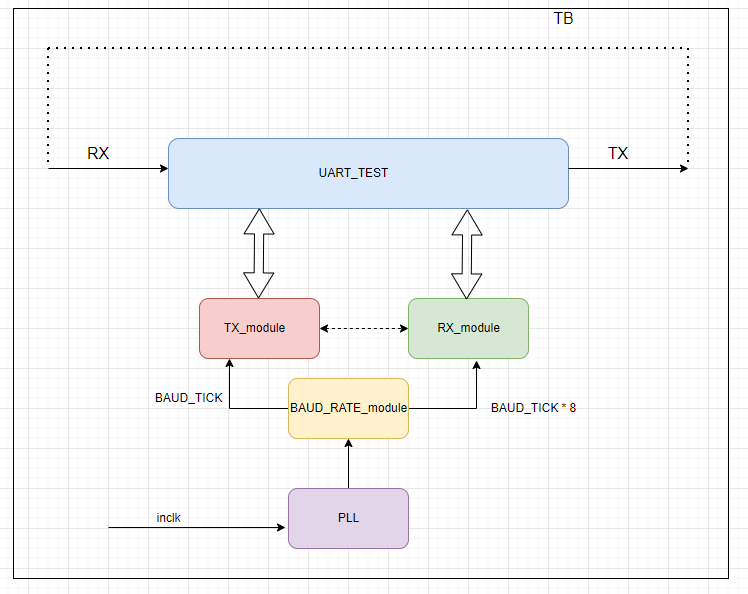
图3
- 仿真程序
|
1 2 3 4 5 6 7 8 9 10 11 12 13 14 15 16 17 18 19 20 21 22 23 24 25 26 27 28 29 30 31 32 33 34 35 36 37 38 39 40 41 |
`timescale 1ns / 1ps module tb ( ); parameter PERIOD = 20 ; //50Mhz reg clk; initial begin clk = 0; #(PERIOD/2); forever #(PERIOD/2) clk = ~clk; end initial begin #2000000; $stop; end wire txrx; test_uart # ( .SIM_DEBUG ( "TRUE") // "TRUE" "FALSE" ) test_uart_inst ( .inclk (clk), .tx (txrx), .rx (txrx) ); endmodule |
- 仿真波形(Modelsim)
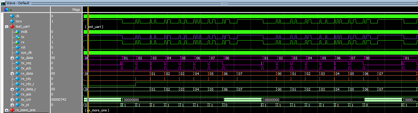
图4
从图4的波形可以看出,经过回环测试,接收数据可以正确接收数据。
二 RXD部分用判多方式
|
1 2 3 4 5 6 7 8 9 10 11 12 13 14 15 16 17 18 19 20 21 22 23 24 25 26 27 28 29 30 31 32 33 34 35 36 37 38 39 40 41 42 43 44 45 46 47 48 49 50 51 52 53 54 55 56 57 58 59 60 61 62 63 64 65 66 67 68 69 70 71 72 73 74 75 76 77 78 79 80 81 82 83 84 85 86 87 88 89 90 91 92 93 94 95 96 97 98 99 100 101 102 103 104 105 106 107 108 109 110 111 112 113 114 115 116 117 118 119 120 121 122 123 124 125 126 127 128 129 130 131 132 133 134 135 136 137 138 139 140 141 142 143 144 145 146 147 148 149 150 151 152 153 154 155 156 157 158 159 160 161 162 163 164 165 166 167 168 169 170 171 172 173 174 175 176 177 178 179 180 181 182 183 184 185 186 187 188 189 190 191 192 193 194 195 196 197 198 199 200 201 202 203 204 205 206 207 208 209 210 211 212 213 214 215 216 217 218 219 220 221 222 223 224 225 226 227 228 229 230 231 232 233 234 235 236 237 238 239 240 241 242 243 244 245 246 247 248 249 250 251 252 253 254 255 256 257 258 259 260 261 262 263 264 265 266 267 268 269 270 271 272 273 274 275 276 277 278 279 280 281 282 283 284 285 286 287 288 289 290 291 292 293 294 295 296 297 298 299 300 301 302 303 304 305 306 307 308 309 310 311 |
`timescale 1ns / 1ps module rx_more_one #( parameter PARITY = "ODD", //"ODD"--odd parity, "EVEN"--even parity, others--no parity parameter STOP_BIT = 1 ) ( input sys_clk, input rst, input rx, input bd8_rate, output reg [7:0] rx_data = 0, output reg rx_rdy = 0 ); localparam [ 3: 0 ] IDLE0 = 0, IDLE1 = 1, START = 2, FIRST_BIT = 3, SEC_BIT = 4, THIRD_BIT = 5, FOUTH_BIT = 6, FIF_BIT = 7, SIX_BIT = 8, SEVN_BIT = 9, EIGTH_BIT = 10, PAR_BIT = 11, STOP1_BIT = 12, STOP2_BIT = 13; localparam EXTRA_COUNT = (PARITY == "ODD"||PARITY == "EVEN") ? 8 : 0; localparam EXTRA_STOP_COUNT = (STOP_BIT == 2) ? 8 : 0; reg [ 1: 0 ] rx_r; reg rx_nedge; // reg [ 7: 0 ] rx_data_tmp; reg rx_rdy_tmp; reg [ 7: 0 ] sample_bit; wire [ 3: 0 ] count_one; wire rx_bit; reg [ 3: 0 ] sample_st_cs, sample_st_ns; reg [ 6: 0 ] sample_count_cs, sample_count_ns; reg [ 6: 0 ] sample_count_cs_r; assign count_one = sample_bit[ 0 ] + sample_bit[ 1 ] + sample_bit[ 2 ] + sample_bit[ 3 ] + sample_bit[ 4 ] + sample_bit[ 5 ] + sample_bit[ 6 ] + sample_bit[ 7 ]; assign rx_bit = ( count_one > 4 ) ? 1'b1 : 1'b0; always@( posedge sys_clk or posedge rst ) if ( rst ) begin rx_r <= 0; rx_nedge <= 0; end else begin if ( bd8_rate ) begin rx_r <= { rx_r[ 0 ], rx }; // rx shift left rx_nedge <= (rx_r == 2'b10) ? 1'b1 : 1'b0; // capture the falling edge end end always@( posedge sys_clk or posedge rst ) if ( rst ) begin sample_st_cs <= IDLE0; end else begin sample_st_cs <= sample_st_ns; end always@( posedge sys_clk or posedge rst ) if ( rst ) begin sample_count_cs <= 0; end else begin sample_count_cs <= sample_count_ns; end always@( * ) begin sample_count_ns = sample_count_cs; sample_st_ns = sample_st_cs; if ( bd8_rate ) begin case ( sample_st_cs ) IDLE0: begin //idle state, waiting for ta least 10bits 1 if ( sample_count_cs == (80 + EXTRA_COUNT + EXTRA_STOP_COUNT ) ) sample_st_ns = IDLE1; else if ( rx_r[ 1 ] ) sample_count_ns = sample_count_cs + 1; else sample_count_ns = 0; end IDLE1: begin //waiting for start_bit's edge sample_count_ns = 0; if ( rx_nedge ) sample_st_ns = START; end START: begin sample_count_ns = sample_count_cs + 1; if ( sample_count_cs == 5 ) begin sample_count_ns = 0; if ( rx_bit ) // sample times bigger than 4 sample_st_ns = IDLE1; // detect start flag else sample_st_ns = FIRST_BIT; end end FIRST_BIT: begin sample_count_ns = sample_count_cs + 1; if ( sample_count_cs == 7 ) begin sample_count_ns = 0; sample_st_ns = SEC_BIT; end end SEC_BIT: begin sample_count_ns = sample_count_cs + 1; if ( sample_count_cs == 7 ) begin sample_count_ns = 0; sample_st_ns = THIRD_BIT; end end THIRD_BIT: begin sample_count_ns = sample_count_cs + 1; if ( sample_count_cs == 7 ) begin sample_count_ns = 0; sample_st_ns = FOUTH_BIT; end end FOUTH_BIT: begin sample_count_ns = sample_count_cs + 1; if ( sample_count_cs == 7 ) begin sample_count_ns = 0; sample_st_ns = FIF_BIT ; end end FIF_BIT: begin sample_count_ns = sample_count_cs + 1; if ( sample_count_cs == 7 ) begin sample_count_ns = 0; sample_st_ns = SIX_BIT; end end SIX_BIT: begin sample_count_ns = sample_count_cs + 1; if ( sample_count_cs == 7 ) begin sample_count_ns = 0; sample_st_ns = SEVN_BIT; end end SEVN_BIT: begin sample_count_ns = sample_count_cs + 1; if ( sample_count_cs == 7 ) begin sample_count_ns = 0; sample_st_ns = EIGTH_BIT; end end EIGTH_BIT: begin sample_count_ns = sample_count_cs + 1; if ( sample_count_cs == 7 ) begin sample_count_ns = 0; if ( ( PARITY == "ODD" ) || ( PARITY == "EVEN" ) ) sample_st_ns = PAR_BIT; else sample_st_ns = STOP1_BIT; end end PAR_BIT: begin sample_count_ns = sample_count_cs + 1; if ( sample_count_cs == 7 ) begin sample_count_ns = 0; sample_st_ns = STOP1_BIT; end end STOP1_BIT: begin sample_count_ns = sample_count_cs + 1; if ( sample_count_cs == 6 ) begin sample_count_ns = 0; if ( STOP_BIT == 2 ) sample_st_ns = STOP2_BIT; else sample_st_ns = IDLE1; end end STOP2_BIT: begin sample_count_ns = sample_count_cs + 1; if ( sample_count_cs == 7 ) begin sample_count_ns = 0; sample_st_ns = IDLE1; end end endcase end end always@( posedge sys_clk or posedge rst ) if ( rst ) begin sample_bit <= 0; rx_rdy_tmp <= 1'b0; rx_data_tmp <= 0; end else begin rx_rdy_tmp <= 1'b0; if ( sample_st_cs == IDLE1 ) sample_bit <= rx_r[ 1 ]; case ( sample_st_cs ) START, FIRST_BIT, SEC_BIT, THIRD_BIT, FOUTH_BIT, FIF_BIT, SIX_BIT, SEVN_BIT, EIGTH_BIT, PAR_BIT, STOP1_BIT, STOP2_BIT : begin if ( bd8_rate ) sample_bit <= { sample_bit[ 6: 0 ], rx_r[ 1 ] }; end endcase sample_count_cs_r <= sample_count_cs; if (( sample_count_cs_r == 7 ) & bd8_rate ) begin //delay one clock case ( sample_st_cs ) FIRST_BIT: rx_data_tmp[ 0 ] <= rx_bit; SEC_BIT: rx_data_tmp[ 1 ] <= rx_bit; THIRD_BIT: rx_data_tmp[ 2 ] <= rx_bit; FOUTH_BIT: rx_data_tmp[ 3 ] <= rx_bit; FIF_BIT: rx_data_tmp[ 4 ] <= rx_bit; SIX_BIT: rx_data_tmp[ 5 ] <= rx_bit; SEVN_BIT: rx_data_tmp[ 6 ] <= rx_bit; EIGTH_BIT: begin rx_data_tmp[ 7 ] <= rx_bit; rx_rdy_tmp <= 1'b1; end default: ; endcase end end always@( posedge sys_clk ) begin if ( rx_rdy_tmp ) begin rx_data <= rx_data_tmp; rx_rdy <= 1'b1; end else rx_rdy <= 1'b0; end endmodule |
加载rx_more_one 变量到仿真波形中,观察其中一位的接收,移位,求和,判多的结果看看是否与预期的设计相符,图5,图6显示了停止位的解码过程。
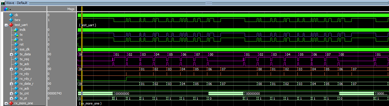
图5
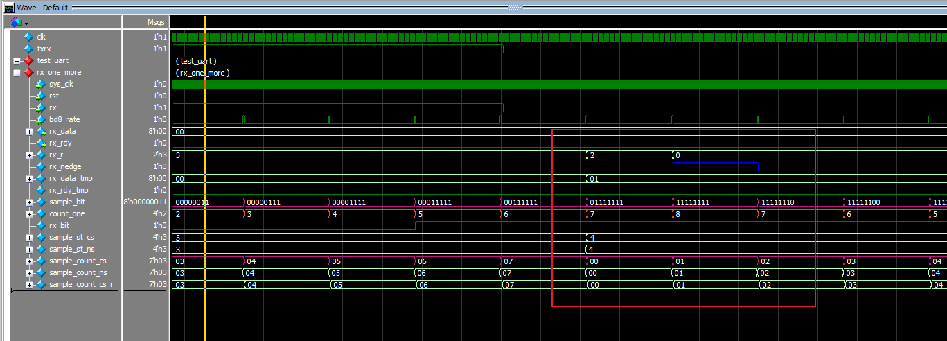
图6
图6的红框标注了sample_bit,count_one,rx_bit与状态机及sample_count_cs之间的逻辑与时序关系。最终测试在停止位解码时,count_one得到8个1,提高了判决的冗余度。
练习题:
- 将奇偶校验设为奇校验,重新仿真,并验证接收数据的正确性。
- 分析对照仿真波形rx_r[1],sample_st_cs, sample_count_cs,sample_bit,count_one,rx_bit的时序关系,并分析在判多时为什么要如下语句出现:
|
1 2 3 4 5 6 7 8 9 10 11 12 13 14 15 16 17 18 19 20 |
sample_count_cs_r <= sample_count_cs; if(sample_count_cs_r == 7) begin //delay one clock case(sample_st_cs) FIRST_BIT: rx_data_tmp[0] = rx_bit; SEC_BIT: rx_data_tmp[1] = rx_bit; THIRD_BIT: rx_data_tmp[2] = rx_bit; FOUTH_BIT: rx_data_tmp[3] = rx_bit; FIF_BIT: rx_data_tmp[4] = rx_bit; SIX_BIT: rx_data_tmp[5] = rx_bit; SEVN_BIT: rx_data_tmp[6] = rx_bit; EIGTH_BIT: begin rx_data_tmp[7] = rx_bit; rx_rdy_tmp = 1'b1; end default:; endcase |
而不是直接采用if(sample_count_cs == 7)begin 的方式实现 ?
工程代码如下:
[content_control]
[/content_control]